良好的顶点数据布局和压缩对于任何图形应用程序的性能都至关重要,无论是 2D 用户界面应用还是大型 3D 开放世界游戏。通过 Android GPU Inspector 的帧分析器对数十款热门 Android 游戏进行的内部测试表明,在顶点数据管理方面还有很多改进空间。我们观察到,顶点数据通常对所有顶点属性使用全精度 32 位浮点值,并且顶点缓冲区布局使用完全交错属性的结构数组。
本文讨论如何使用以下技术优化 Android 应用程序的图形性能:
- 顶点压缩
- 顶点流分割
实施这些技术可以将顶点内存带宽使用率提高多达 50%,减少与 CPU 的内存总线争用,减少系统内存停滞,并延长电池续航时间;所有这些都对开发者和最终用户有利!
所有呈现的数据均来自一个包含约 19,000,000 个顶点并在 Pixel 4 上运行的示例静态场景。
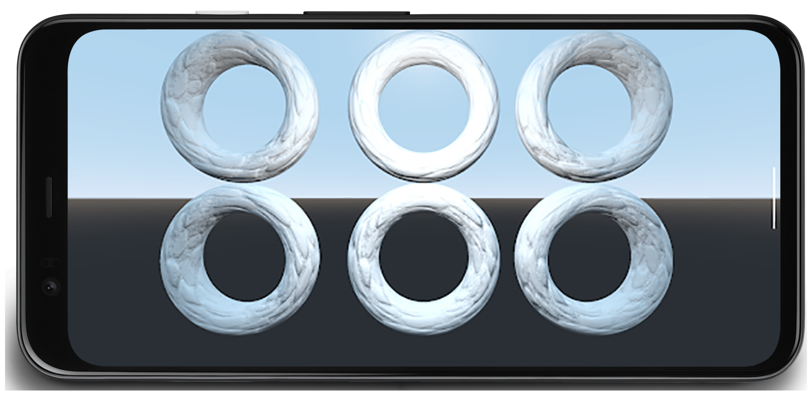
图 1:包含 6 个环和 1900 万个顶点的示例场景
顶点压缩
顶点压缩是一个通用术语,指使用高效打包来减少运行时和存储中顶点数据大小的有损压缩技术。减小顶点大小有多个好处,包括减少 GPU 上的内存带宽(通过计算换取带宽)、提高缓存利用率以及可能降低寄存器溢出的风险。
顶点压缩的常见方法包括:
- 降低顶点数据属性的数值精度(例如:从 32 位浮点数到 16 位浮点数)
- 以不同格式表示属性
例如,如果一个顶点对位置 (vec3)、法线 (vec3) 和纹理坐标 (vec2) 使用完整的 32 位浮点数,那么将所有这些替换为 16 位浮点数将使顶点大小减少 50%(平均 32 字节顶点中减少 16 字节)。
顶点位置
在绝大多数网格中,顶点位置数据可以从全精度 32 位浮点值压缩为半精度 16 位浮点值,并且几乎所有移动设备都支持硬件中的半浮点。将 float32 转换为 float16 的转换函数如下所示(改编自本指南):
uint16_t f32_to_f16(float f) {
  uint32_t x = (uint32_t)f;
  uint32_t sign = (unsigned short)(x >> 31);
  uint32_t mantissa;
  uint32_t exp;
  uint16_t hf;

  mantissa = x & ((1 << 23) - 1);
  exp = x & (0xFF << 23);
  if (exp >= 0x47800000) {
    // check if the original number is a NaN
    if (mantissa && (exp == (0xFF << 23))) {
      // single precision NaN
      mantissa = (1 << 23) - 1;
    } else {
      // half-float will be Inf
      mantissa = 0;
    }
    hf = (((uint16_t)sign) << 15) | (uint16_t)((0x1F << 10)) |
         (uint16_t)(mantissa >> 13);
  }
  // check if exponent is <= -15
  else if (exp <= 0x38000000) {
    hf = 0;  // too small to be represented
  } else {
    hf = (((uint16_t)sign) << 15) | (uint16_t)((exp - 0x38000000) >> 13) |
         (uint16_t)(mantissa >> 13);
  }

  return hf;
}
这种方法有一个限制;精度会随着顶点离原点越来越远而降低,使其不适用于空间上非常大的网格(元素超出 1024 的顶点)。您可以通过将网格分割成更小的块来解决此问题,将每个块围绕模型原点居中,并进行缩放,使每个块的所有顶点都落在 [-1, 1] 范围内,该范围包含浮点值的最高精度。压缩的伪代码如下:
for each position p in Mesh:
   p -= center_of_bounding_box // Moves Mesh back to the center of model space
   p /= half_size_bounding_box // Fits the mesh into a [-1, 1] cube
   vec3<float16> result = vec3(f32_to_f16(p.x), f32_to_f16(p.y), f32_to_f16(p.z));
您将缩放因子和转换烘焙到模型矩阵中,以便在渲染时解压缩顶点数据。请记住,您不希望将此相同的模型矩阵用于转换法线,因为它们没有应用相同的压缩。您将需要一个没有这些解压缩转换的矩阵用于法线,或者您可以使用基本模型矩阵(可以用于法线),然后在着色器中将额外的解压缩转换应用到模型矩阵。一个示例:
vec3 in in_pos;

void main() {
   ...
   // bounding box data packed into uniform buffer
   vec3 decompress_pos = in_pos * half_size_bounding_box + center_of_bounding_box;
   gl_Position = proj * view * model * decompress_pos;
}
另一种方法是使用有符号归一化整数 (SNORM)。SNORM 数据类型使用整数而不是浮点数来表示 [-1, 1] 之间的值。对位置使用 16 位 SNORM 可以获得与 float16 相同的内存节省,而没有非均匀分布的缺点。我们推荐的一种使用 SNORM 的实现如下所示:
const int BITS = 16

for each position p in Mesh:
   p -= center_of_bounding_box // Moves Mesh back to the center of model space
   p /= half_size_bounding_box // Fits the mesh into a [-1, 1] cube
   // float to integer value conversion
   p = clamp(p * (2^(BITS - 1) - 1), -2^(BITS - 1), 2^(BITS - 1) - 1)
| 格式 | 大小 | |
|---|---|---|
| 之前 | vec4<float32> |
16 字节 |
| 之后 | vec3<float16/SNORM16> |
6 字节 |
顶点法线和切线空间
顶点法线是光照所需的,切线空间是法线贴图等更复杂技术所需的。
切线空间
切线空间是一个坐标系,其中每个顶点由法线、切线和副切线向量组成。由于这三个向量通常彼此正交,我们只需要存储其中两个,并且可以通过在顶点着色器中对另外两个进行叉积来计算第三个。
这些向量通常可以使用 16 位浮点数表示,而不会造成任何可感知的视觉保真度损失,所以这是一个很好的开始!
我们可以使用一种称为 QTangents 的技术进一步压缩,该技术将整个切线空间存储在一个四元数中。由于四元数可以用于表示旋转,通过将切线空间向量视为表示旋转的 3x3 矩阵的列向量(在这种情况下是从模型空间到切线空间),我们可以在两者之间进行转换!四元数在数据方面可以视为 vec4,从切线空间向量到基于上面链接的论文和此处实现的改编的 QTangent 转换如下:
const int BITS = 16

quaternion tangent_space_to_quat(vec3 normal, vec3 tangent, vec3 bitangent) {
   mat3 tbn = {normal, tangent, bitangent};
   quaternion qTangent(tbn);
   qTangent.normalize();

   //Make sure QTangent is always positive
   if (qTangent.w < 0)
       qTangent = -qTangent;

   const float bias = 1.0 / (2^(BITS - 1) - 1);

   //Because '-0' sign information is lost when using integers,
   //we need to apply a "bias"; while making sure the Quaternion
   //stays normalized.
   // ** Also our shaders assume qTangent.w is never 0. **
   if (qTangent.w < bias) {
       Real normFactor = Math::Sqrt( 1 - bias * bias );
       qTangent.w = bias;
       qTangent.x *= normFactor;
       qTangent.y *= normFactor;
       qTangent.z *= normFactor;
   }

   //If it's reflected, then make sure .w is negative.
   vec3 naturalBinormal = cross_product(tangent, normal);
   if (dot_product(naturalBinormal, binormal) <= 0)
       qTangent = -qTangent;
   return qTangent;
}
四元数将被标准化,您将能够使用 SNORM 对其进行压缩。16 位 SNORM 提供了良好的精度和内存节省。8 位 SNORM 可以提供更多的节省,但可能会在高光泽材料上引起伪影。您可以尝试两者,看看哪种最适合您的资产!四元数编码如下:
for each vertex v in mesh:
   quaternion res = tangent_space_to_quat(v.normal, v.tangent, v.bitangent);
   // Once we have the quaternion we can compress it
   res = clamp(res * (2^(BITS - 1) - 1), -2^(BITS - 1), 2^(BITS - 1) - 1);
在顶点着色器中解码四元数(改编自此处):
vec3 xAxis( vec4 qQuat )
{
  float fTy  = 2.0 * qQuat.y;
  float fTz  = 2.0 * qQuat.z;
  float fTwy = fTy * qQuat.w;
  float fTwz = fTz * qQuat.w;
  float fTxy = fTy * qQuat.x;
  float fTxz = fTz * qQuat.x;
  float fTyy = fTy * qQuat.y;
  float fTzz = fTz * qQuat.z;

  return vec3( 1.0-(fTyy+fTzz), fTxy+fTwz, fTxz-fTwy );
}

vec3 yAxis( vec4 qQuat )
{
  float fTx  = 2.0 * qQuat.x;
  float fTy  = 2.0 * qQuat.y;
  float fTz  = 2.0 * qQuat.z;
  float fTwx = fTx * qQuat.w;
  float fTwz = fTz * qQuat.w;
  float fTxx = fTx * qQuat.x;
  float fTxy = fTy * qQuat.x;
  float fTyz = fTz * qQuat.y;
  float fTzz = fTz * qQuat.z;

  return vec3( fTxy-fTwz, 1.0-(fTxx+fTzz), fTyz+fTwx );
}

void main() {
  vec4 qtangent = normalize(in_qtangent); //Needed because 16-bit quantization
  vec3 normal = xAxis(qtangent);
  vec3 tangent = yAxis(qtangent);
  float biNormalReflection = sign(in_qtangent.w); //ensured qtangent.w != 0
  vec3 binormal = cross(normal, tangent) * biNormalReflection;
  ...
}
| 格式 | 大小 | |
|---|---|---|
| 之前 | vec3<float32> + vec3<float32> + vec3<float32> |
36 字节 |
| 之后 | vec4<SNORM16> |
8 字节 |
仅法线
如果您只需要存储法线向量,还有另一种方法可以带来更多节省——使用单位向量的八面体映射而不是笛卡尔坐标来压缩法线向量。八面体映射的工作原理是将单位球体投影到八面体上,然后将八面体投影到 2D 平面上。结果是您可以使用两个数字表示任何法线向量。这两个数字可以被认为是纹理坐标,我们用它来“采样”我们投影球体的 2D 平面,从而恢复原始向量。这两个数字可以存储在 SNORM8 中。

图 2:八面体映射可视化(来源)
const int BITS = 8

// Assumes the vector is unit length
// sign() function should return positive for 0
for each normal n in mesh:
  float invL1Norm = 1.0 / (abs(n.x) + abs(n.y) + abs(n.z));
  vec2 res;
  if (n.z < 0.0) {
    res.x = (1.0 - abs(n.y * invL1Norm)) * sign(n.x);
    res.y = (1.0 - abs(n.x * invL1Norm)) * sign(n.y);
  } else {
    res.x = n.x * invL1Norm;
    res.y = n.y * invL1Norm;
  }
  res = clamp(res * (2^(BITS - 1) - 1), -2^(BITS - 1), 2^(BITS - 1) - 1)
在顶点着色器中解压缩(转换回笛卡尔坐标)的成本很低;在大多数现代移动设备上,我们没有看到实施此技术时出现任何重大的性能下降。顶点着色器中的解压缩:
//Additional Optimization: twitter.com/Stubbesaurus/status/937994790553227264
vec3 oct_to_vec(vec2 e):
  vec3 v = vec3(e.xy, 1.0 - abs(e.x) - abs(e.y));
  float t = max(-v.z, 0.0);
  v.xy += t * -sign(v.xy);
  return v;
这种方法也可以用来存储整个切线空间,使用此技术存储法线和切线向量,使用 vec2<SNORM8>,但您需要找到一种方法来存储副切线的方向(对于您在模型上具有镜像 UV 坐标的常见场景需要)。一种实现方式是将切线向量编码的一个分量映射为始终为正,然后如果您需要翻转副切线方向,则翻转其符号并在顶点着色器中进行检查。
const int BITS = 8
const float bias = 1.0 / (2^(BITS - 1) - 1)

// Compressing
for each normal n in mesh:
  //encode to octahedron, result in range [-1, 1]
  vec2 res = vec_to_oct(n);

  // map y to always be positive
  res.y = res.y * 0.5 + 0.5;

  // add a bias so that y is never 0 (sign in the vertex shader)
  if (res.y < bias)
    res.y = bias;

  // Apply the sign of the binormal to y, which was computed elsewhere
  if (binormal_sign < 0)
    res.y *= -1;

  res = clamp(res * (2^(BITS - 1) - 1), -2^(BITS - 1), 2^(BITS - 1) - 1)
// Vertex shader decompression
vec2 encode = vec2(tangent_encoded.x, abs(tangent_encoded.y) * 2.0 - 1.0));
vec3 tangent_real = oct_to_vec3(encode);
float binormal_sign = sign(tangent_encode.y);
| 格式 | 大小 | |
|---|---|---|
| 之前 | vec3<float32> |
12 字节 |
| 之后 | vec2<SNORM8> |
2 字节 |
顶点 UV 坐标
用于纹理映射(以及其他用途)的 UV 坐标通常使用 32 位浮点数存储。使用 16 位浮点数对其进行压缩会导致大于 1024x1024 的纹理出现精度问题;[0.5, 1.0] 之间的浮点精度意味着值将以大于 1 像素的增量递增!
更好的方法是使用无符号归一化整数 (UNORM),特别是 UNORM16;这在整个纹理坐标范围内提供均匀分布,支持高达 65536x65536 的纹理!这假设每个元素的纹理坐标都在 [0.0, 1.0] 范围内,根据网格的不同,情况可能并非如此(例如,墙壁可以使用超出 1.0 的环绕纹理坐标),因此在查看此技术时请记住这一点。转换函数将如下所示:
const int BITS = 16

for each vertex_uv V in mesh:
  V *= clamp(2^BITS - 1, 0, 2^BITS - 1);  // float to integer value conversion
| 格式 | 大小 | |
|---|---|---|
| 之前 | vec2<float32> |
8 字节 |
| 之后 | vec2<UNORM16> |
4 字节 |
顶点压缩结果
这些顶点压缩技术使顶点内存存储减少了 66%,从 48 字节降至 16 字节。这表现为:
- 顶点内存读取带宽
- 分箱:从 27GB/s 到 9GB/s
- 渲染:从 4.5B/s 到 1.5GB/s
- 顶点提取停滞
- 分箱:从 50% 到 0%
- 渲染:从 90% 到 90%
- 平均字节/顶点
- 分箱:从 48B 到 16B
- 渲染:从 52B 到 18B
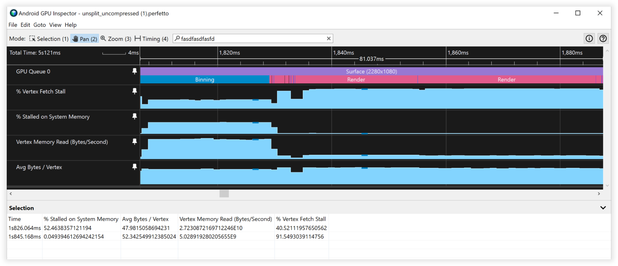
图 3:Android GPU Inspector 中未压缩顶点的视图
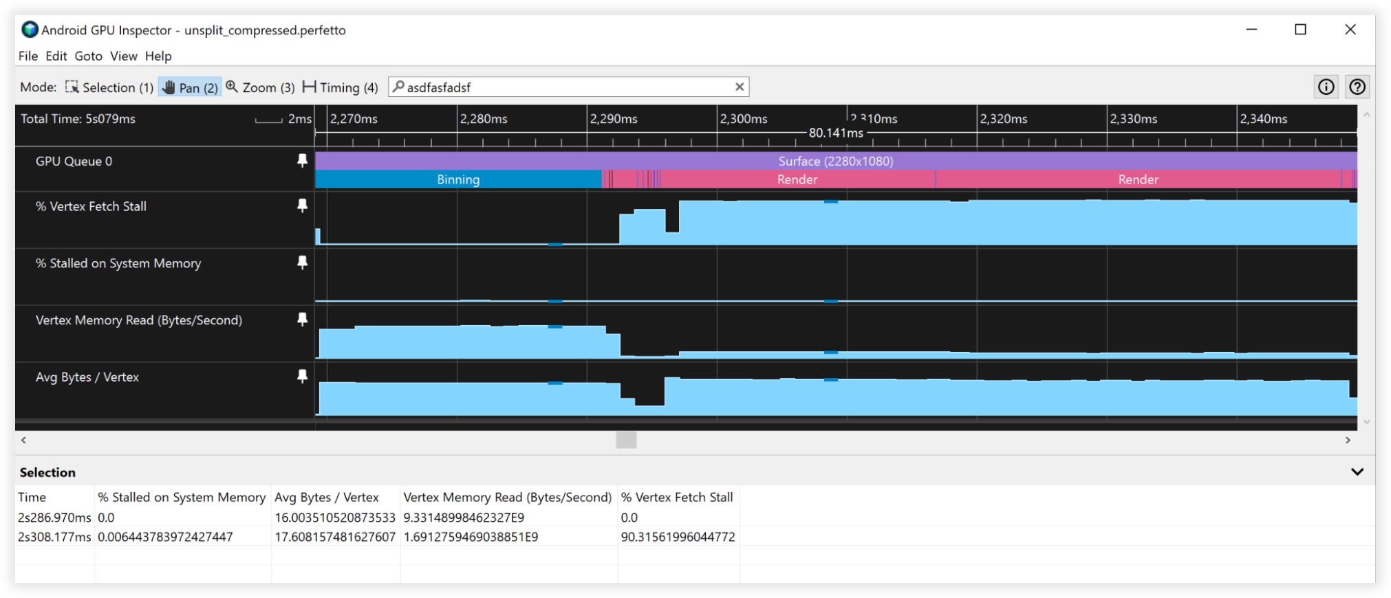
图 4:Android GPU Inspector 中压缩顶点的视图
顶点流分割
顶点流分割优化了顶点缓冲区中的数据组织。这是一种缓存性能优化,对通常在 Android 设备中发现的基于图块的 GPU 有显著影响——尤其是在渲染过程的分箱步骤中。
基于图块的 GPU 会创建一个着色器,根据提供的顶点着色器计算归一化设备坐标以进行分箱。它首先在场景中的每个顶点上执行,无论是否可见。因此,将顶点位置数据在内存中保持连续是一个很大的优势。这种顶点流布局在阴影通道中也可能很有益,因为通常您只需要位置数据用于阴影计算,以及深度预通道(这是一种通常用于控制台/桌面渲染的技术);这种顶点流布局对渲染引擎的多种类别都有好处!
流分割涉及将顶点缓冲区设置为连续的顶点位置数据部分和包含交错顶点属性的另一个部分。大多数应用程序通常将其缓冲区设置为完全交错所有属性。此可视化解释了差异:
Before:
|Position1/Normal1/Tangent1/UV1/Position2/Normal2/Tangent2/UV2......|

After:
|Position1/Position2...|Normal1/Tangent1/UV1/Normal2/Tangent2/UV2...|
了解 GPU 如何获取顶点数据有助于我们理解流分割的好处。假设为了论证:
- 32 字节缓存行(一个非常常见的尺寸)
- 顶点格式包括:
- 位置,vec3<float32> = 12 字节
- 法线 vec3<float32> = 12 字节
- UV 坐标 vec2<float32> = 8 字节
- 总大小 = 32 字节
当 GPU 从内存中获取数据进行分箱时,它将拉取一个 32 字节的缓存行进行操作。如果没有顶点流分割,它只会实际使用该缓存行的前 12 字节进行分箱,并在获取下一个顶点时丢弃其余的 20 字节。有了顶点流分割,顶点位置将在内存中连续,因此当该 32 字节块被拉入缓存时,它将实际包含 2 个完整的顶点位置可供操作,然后才需要返回主内存获取更多数据,效率提高了 2 倍!
现在,如果我们将顶点流分割与顶点压缩结合起来,我们将把单个顶点位置的大小减少到 6 字节,因此从系统内存中拉取的单个 32 字节缓存行将有 5 个完整的顶点位置可供操作,效率提高了 5 倍!
顶点流分割结果
- 顶点内存读取带宽
- 分箱:从 27GB/s 到 6.5GB/s
- 渲染:从 4.5GB/s 到 4.5GB/s
- 顶点提取停滞
- 分箱:从 40% 到 0%
- 渲染:从 90% 到 90%
- 平均字节/顶点
- 分箱:从 48B 到 12B
- 渲染:从 52B 到 52B

图 5:Android GPU Inspector 中未分割顶点流的视图
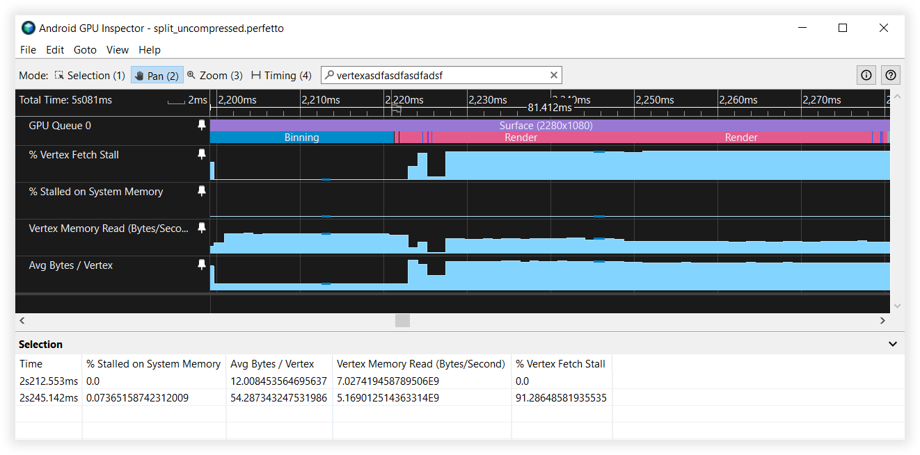
图 6:Android GPU Inspector 中已分割顶点流的视图
复合结果
- 顶点内存读取带宽
- 分箱:从 25GB/s 到 4.5GB/s
- 渲染:从 4.5GB/s 到 1.7GB/s
- 顶点提取停滞
- 分箱:从 41% 到 0%
- 渲染:从 90% 到 90%
- 平均字节/顶点
- 分箱:从 48B 到 8B
- 渲染:从 52B 到 19B

图 7:Android GPU Inspector 中未分割、未压缩顶点流的视图
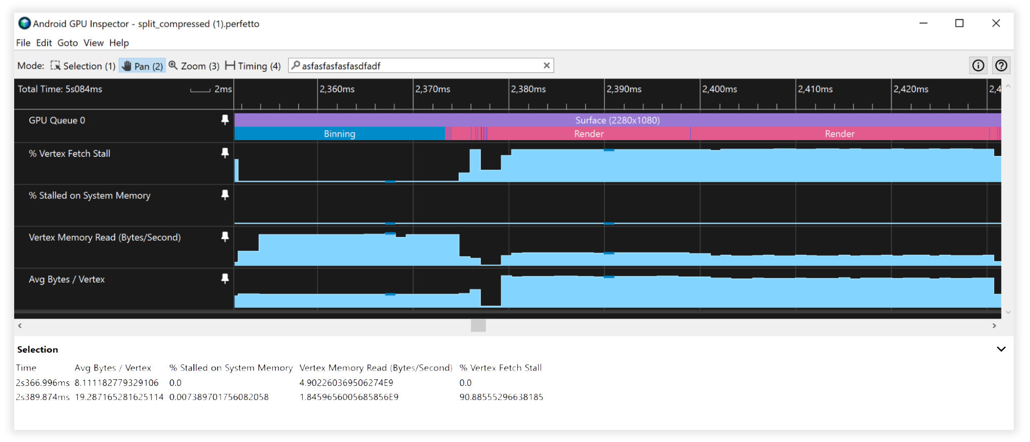
图 8:Android GPU Inspector 中已分割、已压缩顶点流的视图
其他注意事项
16 位 vs 32 位索引缓冲区数据
- 始终分割/分块网格,使其适合 16 位索引缓冲区(最多 65536 个唯一顶点)。这将有助于移动设备上的索引渲染,因为它获取顶点数据的成本更低,并且会消耗更少的电量。
不支持的顶点缓冲区属性格式
- SSCALED 顶点格式在移动设备上并未得到广泛支持,并且在使用时,如果驱动程序没有硬件支持而尝试模拟它们,可能会导致昂贵的性能权衡。始终选择 SNORM 并支付可忽略的 ALU 成本进行解压缩。
